See the product

See the product
See the product
See the product
See the product
See the product
See the product
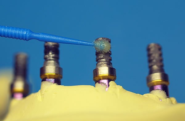 |  | 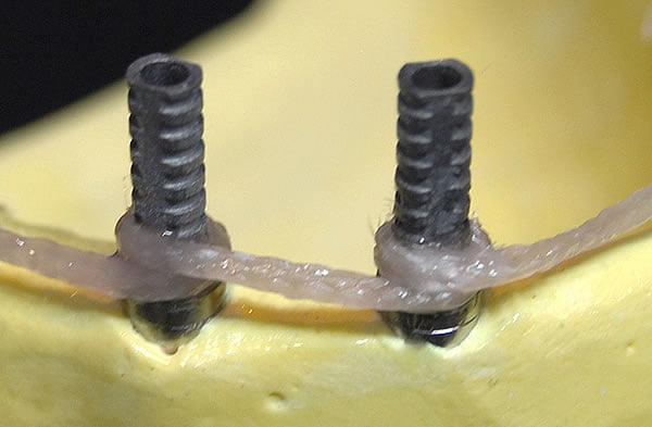 |
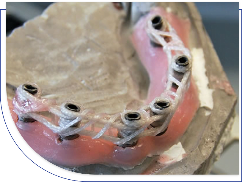
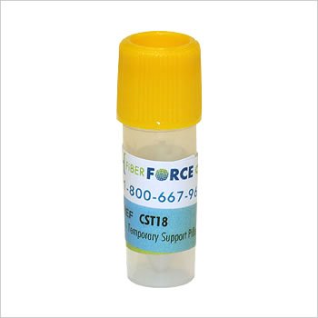
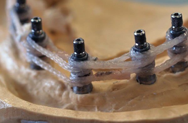
1. Preparation of Titanium CylindersIn order to ensure an effective bond of the CST® fibers to the titanium cylinders, the cylinders are sandblasted with aluminum oxide or Rokatec, silanated and treated with a bonding agent. | 2. Temporary Support PillarsThe CST® temporary support pillars provide two functions. They act as a purchase point from which the CST® fibers are woven into the desired configuration while maintaining tension on the fibers. They also allow for the demarcation and creation of the support structures for the distal extensions. | 3. Wrapping CylindersIn combination with proper surface preparation of titanium cylinders, wrapping the CST® fibers 360 degrees around the cylinders assures that the fibers adhere to the cylinder surface and keeps the complete CST® framework from slipping around the fixed cylinder positions when exposed to stress forces. |
 | 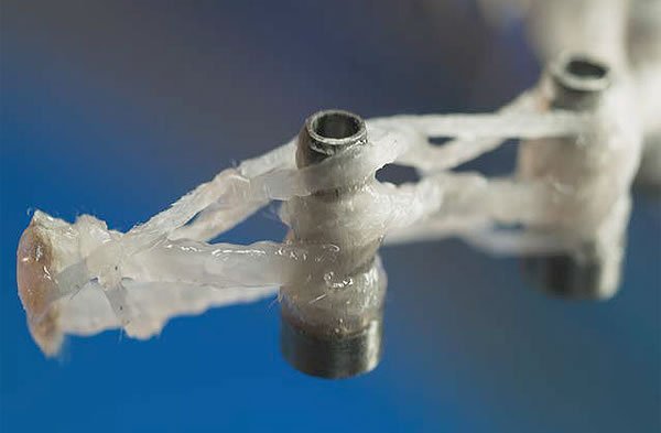 |  |
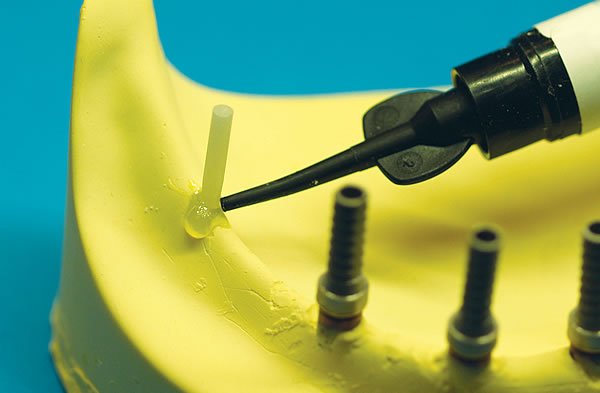
4. Primary Cable StructureThe foundation of the CST® framework is the creation of a three dimensional fiber base cable structure using the 1:6 hybrid compressible fibers. Three cable “runs” are made resulting in a solid fiber base around which acrylic will be processed. This base fiber structure is resistant to the compressive forces delivered to the framework intra-orally. | 5. Distal ExtensionAs the CST® fibers are wrapped around the temporary support pillars a fiber structure is created that will reinforce the acrylic in the area of the distal extension. The third cable run is made at a 45 degree angle, and by applying known engineering principles, maximizes the resistance to stress forces in that area. The maximum recommended length of distal extension in a CST® case is 11mm. | 6. Cable StaysThe 1:4 hybrid compressible fiber is applied in two “back and forth” runs and wrapped around the base structure. This provides additional reinforcement and resistance to eccentric or chewing forces. |
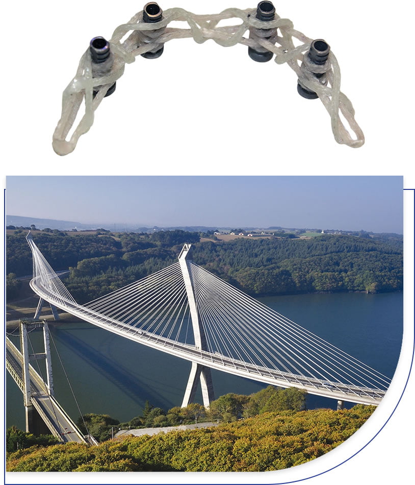
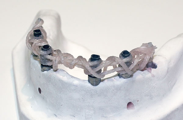
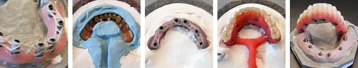
7. Passivity of FitPassivity of fit is essential in implant cases and the CST® technique results in fiber frameworks that are completely passive. | 8. Finished FrameworkOnce light cured the finished CST® framework is now ready to be processed with acrylic using the preferred processing method and following usual protocols. |
The use of fiber reinforced composites (FRC) has entrenched itself in dentistry, like many other industries, due to the physical advantages that FRC have over the metals that have been used historically, be it stainless steel, chrome cobalt, or titanium. FRC combine a very high tensile strength with a low modulus of elasticity making them ideal to resist the repetitive stress forces seen intra orally. Glass fiber posts, like the BIOLIGHT® line of posts, have become the new standard for pre-fabricated endodontic posts due to their physical strength and high level of physical compatibility with tooth structure. FiBER FORCE® rope and mesh fibers have proven themselves to be very effective at reinforcing dentures and other intra-oral appliances, far more so than metals.
| MATERIAL | TENSILE STRENGHT (MPa) | YOUNG’S ELASTIC MODULUS (GPa) |
| E-Glass | 2000 | 80 |
| Steel | 531 | 200 |
| Titanium alloy | 900 | 105-120 |
| Stainless steel | 860 | 195 |
| Chrome – Cobalt | 750 | 225 |
| Chrome – Nickel | 570 | 170 |
| Enamel | 10 | 100 |
| Dentin | 100 | 20 |
| Cortical Bone | 170 | 20 |
| PMMA | 70 | 6 |
CST® fibers are made of e-glass and UDMA resin. This strong matrix allows the fiber matrix to chemically bond with the acrylic or composite materials into which the fibers are integrated. Unlike metal, which can in some cases weaken the acrylic or composite into which it is integrated, the net result is a real reinforcement and improvement in the resistance to stress forces of the final appliance. Internal data shows that acrylic reinforced with fiber mesh, for example, is 2.5 times (150%) more resistant to a repeated stress before showing any signs of damage than acrylic reinforced with metal mesh.
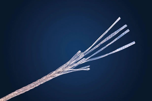
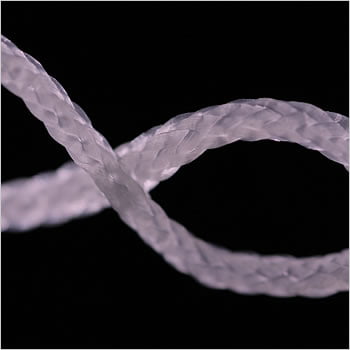
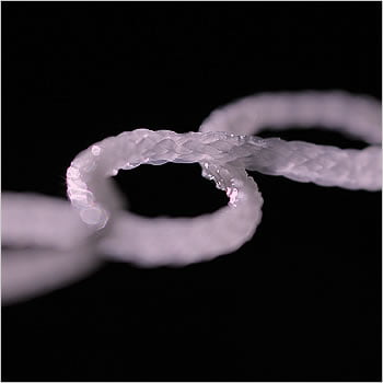
CST® fibers are specially designed for extra toughness and strength. Traditional glass fibers strands come in either a braided format or a uni-directional (UD) format. The innovation with CST® fibers is a combined UD-Braided construction which maximizes physical strength and maintains positive handling characteristics – we call them hybrid compressible fibers. CST® hybrid compressible fibers have 330% more tensile strength than traditional braided fiber rope of a similar dimension and volume. Tensile strength is a key component in determining a materials overall resistance to stress forces.
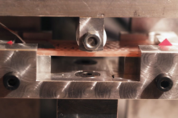
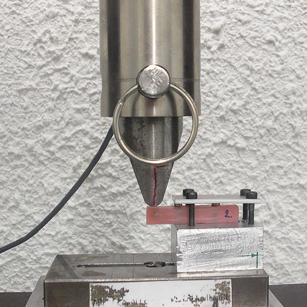
Testing[1] of the CST® concept demonstrates that CST® implant frameworks are 1.65 times stronger than frameworks with no reinforcement when subjected to an increasing three-point load. They also compare well with titanium frameworks and show a greater resistance to stress forces before the acrylic starts to show signs of de-cohesion. This validates the impacts and benefits of the fibers and acrylic working together and resulting in a more natural distribution of stress forces across and within the mass of the appliance.
| Unreinforced samples | Titanium bar | CST® reinforced | |
| Acrylic decohesion | 245 | 337 | 405 |
| Acrylic fracture | 301 | 454 | 405 |
It’s interesting to note that in all three groups tested (unreinforced, titanium and CST®) the amount of force required to create damage to the acrylic far exceeded even the greatest amount of force that can be applied in the posterior portion of the mouth – 50 dNA.[2] All the results taken together suggests that problems that are seen intra-orally with fixed/removable hybrid dentures are more related to the acrylic fatiguing and weakening over time and/or the incompatibility of the acrylic with the metal sub-structure. CST® offers a solution to both challenges as it truly reinforces the acrylic and is chemically and physically compatible with it.
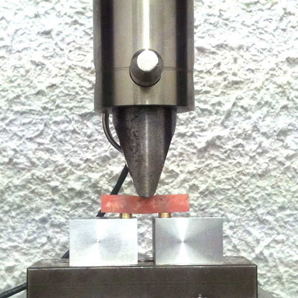
While the maximum length of the distal extension for any fixed appliance is still a question of debate and more complex than popular measures such as the A-P spread, there is no debate that the distal extension is an area of concern as it relates to the durability and longevity of an implant-supported appliance appliance, as well as the health of the implants placed.
A study[1] of the durability of the distal extension has demonstrated that a CST® framework will resist a force of 92 daN before acrylic failure – three times or 200% more force than an acrylic-only framework. In this case the distal extension was 11mm, which is the maximum recommended length of the distal extension with a CST® fiber framework.
[1] – Internal testing
[2] – J. F. BATES, G. D. STAFFORD and A. HARRISON. Masticatory function-a review of the literature: (II) Speed of movement of the mandible, rate of chewing and forces developed in chewing. Journal of Oral Rehabilitation, October 1975, Volume 2, Issue 4, 349-361.